SOLUTIONS / NOGRR 282 RIDE-THROUGH
NOGRR 282 ride-through for AI data centers.
ERCOT requires large computational loads to stay connected through voltage and frequency disturbances. In dual conversion the battery carries the load through the fault. In parallel the hall's own UPS carries the computers, and the battery returns the site's draw to its pre-fault level when the voltage comes back. Two scenario models below show the event from both sides of the connection.
01 / THE RULE
Large computational loads must ride through, not trip.
In ERCOT, Nodal Operating Guide Revision Request (NOGRR) 282, in force since August 1, 2026, sets voltage and frequency ride-through requirements for large computational loads: under Nodal Protocol Revision Request (NPRR) 1308, sites of 75 MW and above where at least half the demand is computational load. The load must stay connected through the voltage and frequency envelope the guide defines, and return to at least 90 percent of its pre-disturbance consumption within 2 seconds of voltage returning above 0.9 per unit. A site that rides through by transferring its load to its own uninterruptible power supply (UPS) and back is held to a stricter clock: it must begin returning to the grid within 0.25 seconds and reach 90 percent within 0.5 seconds (Nodal Operating Guide Section 2.15(3)(e)).
The reason is grid stability. If hundreds of megawatts of data center load drop off the grid at the moment of a fault and come back in a block, the grid frequency and voltage swing beyond what generation can hold. Outside ERCOT, the North American Electric Reliability Corporation (NERC) issued a Level 3 alert on computational loads on May 4, 2026, and the Federal Energy Regulatory Commission (FERC), in Docket RD26-7-000, has directed NERC to file reliability standards for computational loads by December 31, 2026.
The Battalion medium-voltage UPS is fully compatible with grid-fault ride-through interconnection rules such as NOGRR 282. The exact envelope, recovery timing and reactive-power settings are confirmed for each site in its interconnection study.
02 / DUAL CONVERSION
The load never sees the fault.
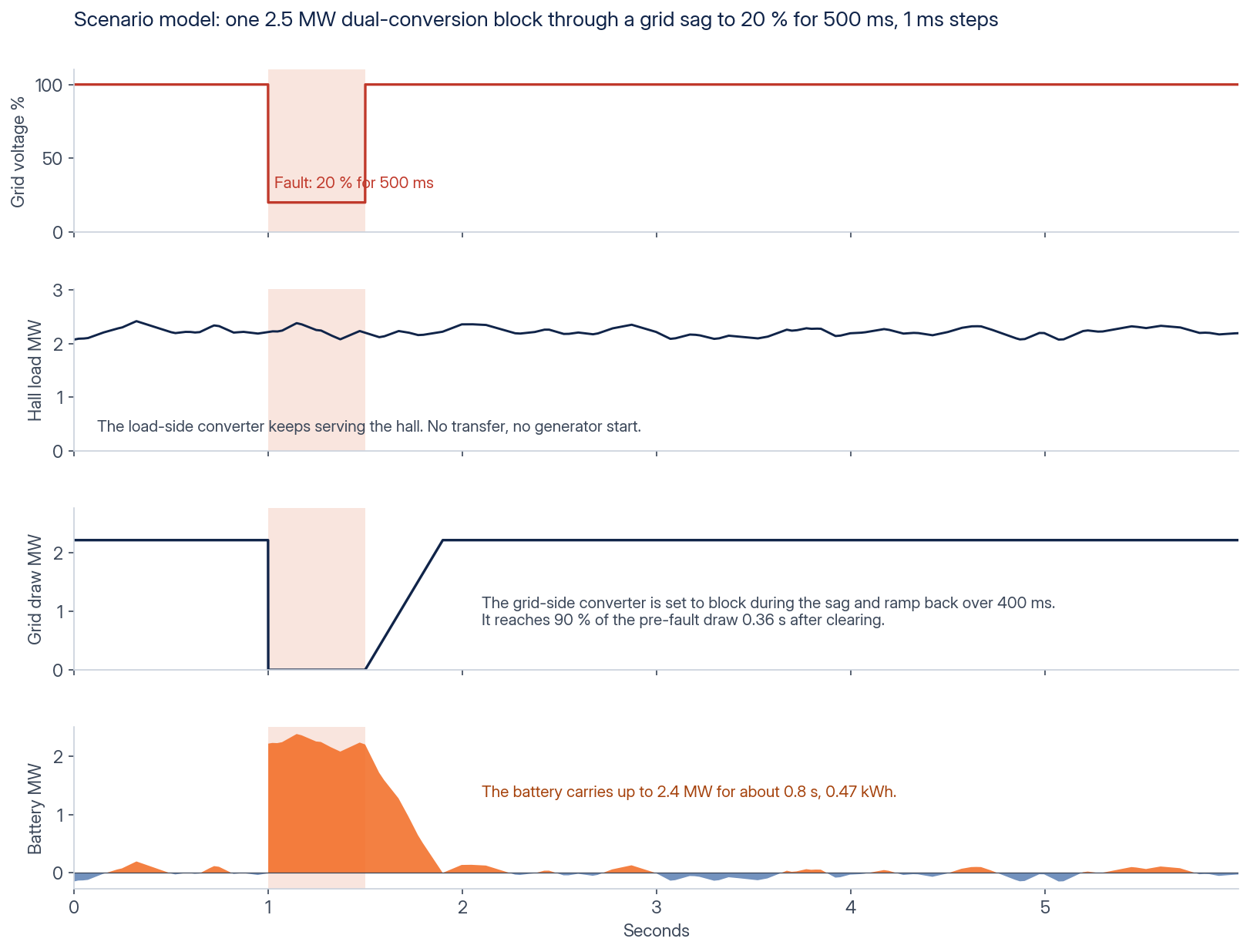
In a dual-conversion block the data center is fed by its own grid-forming converter, which draws from a direct-current (DC) bus that the battery and the grid-side converter share. A grid fault reaches the grid-side converter and stops there. The load-side converter keeps forming voltage for the data center from the battery, with no transfer, no generator start and no interruption.
03 / PARALLEL CONNECTION
The hall UPS carries the computers. The blocks restore the draw.
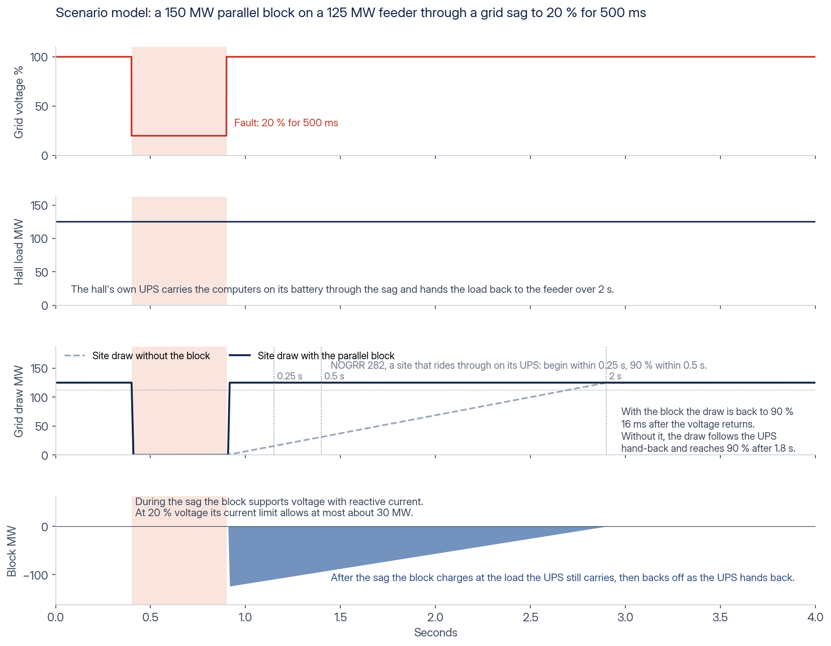
In a parallel connection the hall keeps its own uninterruptible power supply (UPS), and the blocks sit beside it on the medium-voltage feeder. During a deep sag, such as the 20 percent scenario below, the hall’s UPS carries the computers on its own batteries. A block does not take over the hall load: a converter’s current is limited near its rating, so at 20 percent voltage a block can exchange at most about 20 percent of its rated power. The blocks stay connected and support the feeder voltage with reactive current. The site’s draw falls during the sag, as every load’s does, and falls further where the hall’s UPS moves its load onto its own batteries.
In the scenario model, when the voltage returns, the blocks absorb power equal to the load the hall’s UPS still carries within about one cycle (about 17 ms at 60 Hz), up to the blocks’ rated power and with charge headroom held for it. The site’s draw is then back at its pre-fault level, well inside the 0.5 s NOGRR 282 allows. The blocks reduce their charging as the hall’s UPS hands its load back, however long that takes. The interconnection study confirms the recovery for each site.
04 / WHAT WE CONFIRM PER SITE
Envelope, recovery and reactive support.
The site interconnection study sets the voltage and frequency envelope the load must ride through, the recovery rate after clearing, the reactive power the converters supply while the grid is connected, and how the block behaves if the fault turns into a sustained loss of supply. For a parallel connection it also sets the current the site draws during the sag, how the hall’s UPS behaves in repeated sags, and the metering point at which the blocks and the halls are measured. In the distributed parallel concept the blocks can island their feeder section and hold voltage and frequency, within their rating and duration. In dual conversion the load keeps running on the battery for the duration the reserve allows.
Bring the single-line diagram, the load profile with its time resolution and the interconnection agreement. Request information to start that review. The AI data center solution page covers the other duties of the same block, and the ERCOT large-load power-variation limit is on the power smoothing page.
YOUR PROJECT
Request information
Tell us what you are evaluating. An engineer will review your request.
Request information
Request received.
An engineer reviews every request and replies to approved company addresses within one business day.
Your email draft is ready. Send it to complete your request. If your mail client did not open, open the request email or email contact@battalion.energy from your company address with the same details.