AI data centers. Critical power at medium voltage.
Graphics processing unit (GPU) and tensor processing unit (TPU) clusters can swing tens of percent of facility load in under a second, every 20 seconds or so, thousands of times a day. Utilities respond with ramp and variability limits in interconnection agreements and ride-through rules for large loads. A voltage sag that trips rack power supplies forces training to restart from its last checkpoint.
CONTROL
A battery on the medium-voltage bus.
Battalion places a battery energy storage system (BESS) on the medium-voltage bus, with the energy management system (EMS) coordinating the load and the grid. The site’s distribution and ride-through duty select the connection.
Battalion builds both parallel and dual-conversion medium-voltage uninterruptible power supply (UPS) systems on one platform.
AI LOAD PULSES
One training job moves the whole campus.
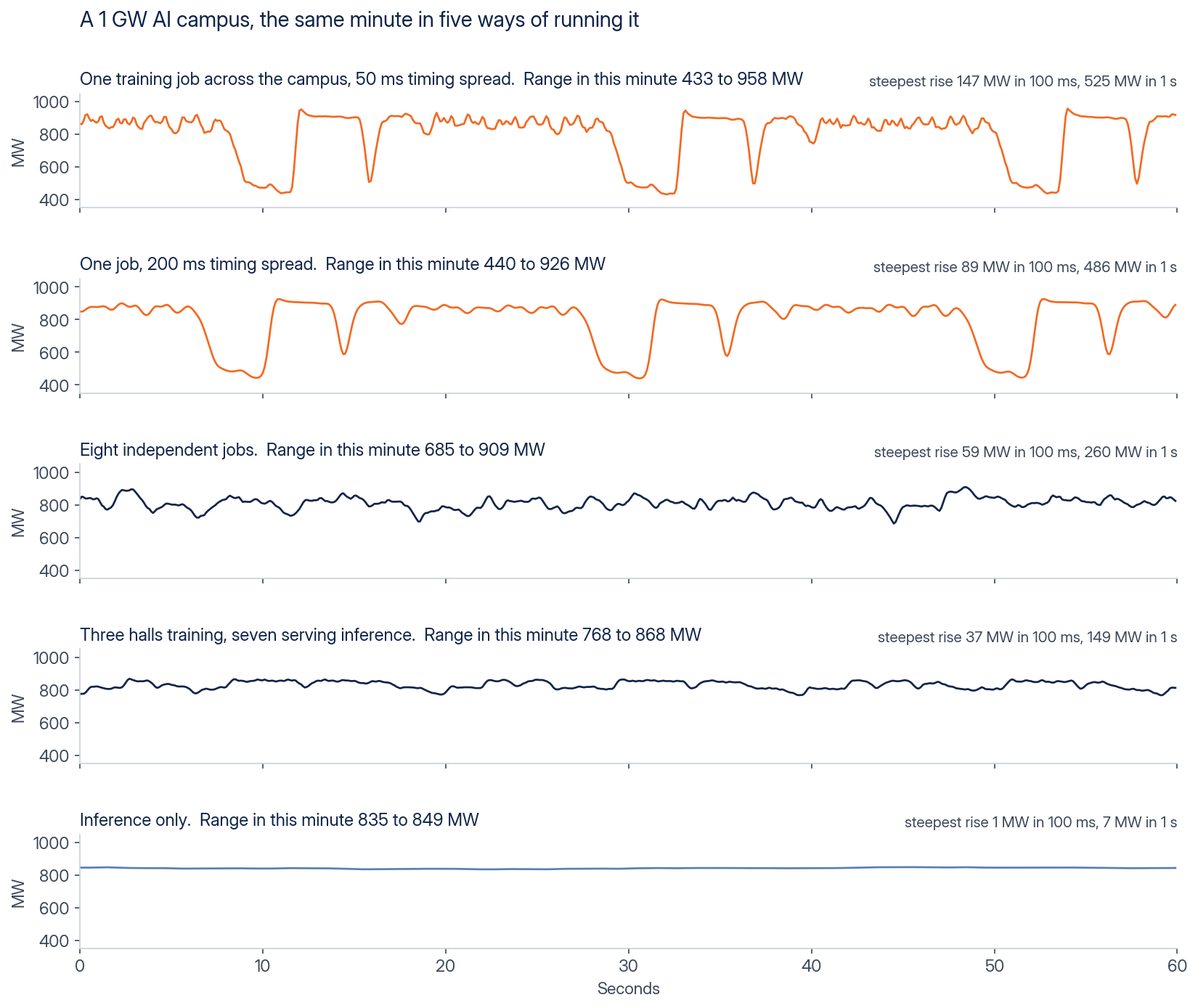
A training job runs in steps. The GPUs compute, pause together while they exchange results, then compute again. Every GPU in the job moves at the same moment, so when one job spans the campus, the whole campus moves with it. At 1 GW the load falls from about 970 MW to about 425 MW and comes back every 20 seconds or so, with rises of up to 147 MW in 100 ms and 525 MW in one second.
Timing differences between racks do not average this away, because the job re-synchronizes at every exchange. With 200 ms of spread the campus still swings from about 440 to 930 MW. Independent jobs and inference smooth the load: eight independent jobs move about 260 MW in a second, and three training halls among seven inference halls about 150 MW.
ENERGENCE / AI LOAD PULSE SCENARIOS, 1 GW CAMPUSA 1 GW campus with 600 MW of IT and 400 MW of cooling and mechanical load, the same minute in five ways of running it, at 100 ms. The training load shape is digitized from a published figure of a GPU training cluster (Choukse et al., arXiv 2508.14318, 2025) and interpolated to 1 ms for the simulation, so rise figures below 100 ms are upper bounds of the digitized source. Inference is a simulated facility day at 1-minute resolution published by the National Laboratory of the Rockies, so it shows no sub-minute variation.
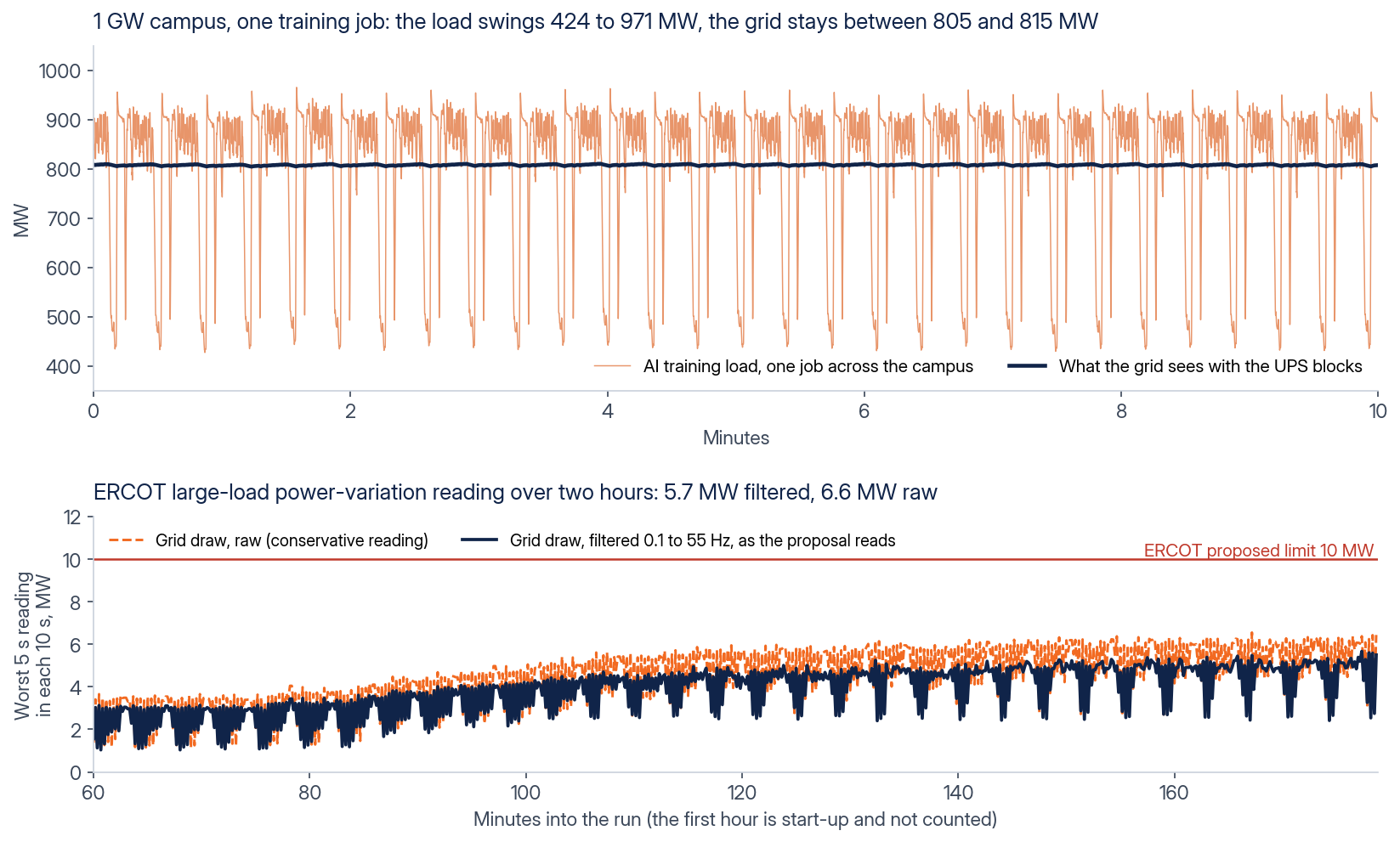
With dual-conversion UPS blocks the grid sees about 1 percent of the swing. The load-side converters serve every pulse from the battery and the grid-side converters follow a slow average, so the grid draw stays between 805 and 815 MW while the campus swings between 424 and 971 MW. On ERCOT’s proposed large-load limit of 10 MW peak to peak in any 5 seconds, the grid draw reads 5.7 MW filtered and 6.6 MW raw over two hours. Parallel blocks give the same reading in the same 1 GW case: beside the load, with a 3 ms total response from measurement through command to the converter, they inject and absorb the opposite of each pulse and read 5.7 MW filtered and 6.6 MW raw.
ENERGENCE / ONE TRAINING JOB, 1 GW CAMPUSOne training job across a 1 GW campus with 50 ms of timing spread, simulated at 1 ms with the production control algorithm. Dual-conversion blocks sized to the load, 1,000 MW with 2 hours of energy. The reading is taken over the last two hours of a three-hour run, after start-up.
TWO DECISIONS
The backup equipment and grid requirements set the starting point.
First, establish whether the project will keep or replace its low-voltage UPS and generators. Dual conversion feeds each load section through its own load-side converter with 0 ms transfer, so it can take the place of the low-voltage UPS. It can take the place of the standby generators only where the battery duration, 1 to 4 hours or custom on request, covers the site’s continuity requirement, which is the owner’s decision. Parallel blocks sit beside the load, on each medium-voltage feeder or at the substation bus, and the halls keep their UPS and generators. The existing distribution, load tolerance and required continuity determine which equipment remains and where the battery connects.
Second, identify the applicable grid requirements. In ERCOT, Nodal Operating Guide Revision Request (NOGRR) 282, in force since August 1, 2026, sets voltage and frequency ride-through requirements for large computational loads: under Nodal Protocol Revision Request (NPRR) 1308, sites of 75 MW and above where at least half the demand is computational load. ERCOT has also proposed a large-load power-variation limit of 10 MW in any 5 seconds, which it has not yet adopted. The Battalion medium-voltage UPS is fully compatible with grid-fault ride-through interconnection rules such as NOGRR 282. For another independent system operator (ISO), bring its ride-through requirements and the interconnection agreement into the study.
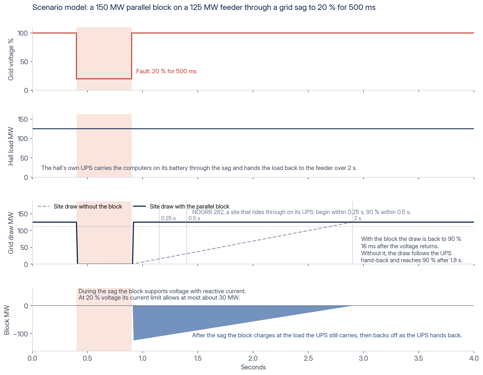
A site that keeps its UPS and generators but must meet a ride-through rule, or is planning for the power-variation limit, can use parallel blocks. They smooth the load pulses at the grid connection, with the same reading as dual conversion in the 1 GW case above. In a deep grid sag the halls’ UPS carries the computers. In the scenario model, blocks sized for the hall load return the site’s draw to its pre-fault level within about one cycle of the voltage returning, well inside the 0.5 s NOGRR 282 allows. The interconnection study confirms the recovery for each site. They also protect generators that share their medium-voltage bus from the pulses. The medium-voltage UPS page compares the two configurations line by line.
CONNECTION
Four ways to connect the battery.
The battery can sit in parallel with the load, centralized at the substation or distributed on each feeder, or in series with it as a dual-conversion block, per load section or on a shared protected bus. The existing distribution, the ride-through requirement and the battery duty set the choice, and the options can be combined on one site. The medium-voltage UPS page shows the four concepts and the availability design basis.
GRID FUNCTIONS
Power shaped at the connection.
Three functions of the same block. Smoothing and ramp traces are simulations of the production control code. Ride-through traces are scenario models.
01 / RIDE-THROUGH
The site rides through a grid disturbance.
In ERCOT, Nodal Operating Guide Revision Request (NOGRR) 282, in force since August 1, 2026, sets voltage and frequency ride-through requirements for large computational loads: under Nodal Protocol Revision Request (NPRR) 1308, sites of 75 MW and above where at least half the demand is computational load. The Battalion medium-voltage UPS is fully compatible with grid-fault ride-through interconnection rules such as NOGRR 282, with the settings confirmed for each site in its interconnection study.
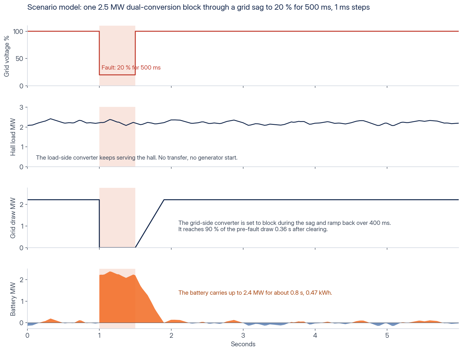
In dual conversion the load is fed through its own converter, with the battery on the direct-current (DC) bus, so a grid disturbance does not reach it. In a parallel connection the halls' own UPS carries the computers through a deep sag. The blocks stay connected and support the feeder voltage. In the scenario model, the blocks return the site's draw to its pre-fault level within about one cycle of the voltage returning, well inside the 0.5 s NOGRR 282 allows. The interconnection study confirms the recovery for each site. If the supply is lost, distributed blocks can island their section.
After separation from the grid, local block control holds the section at nominal voltage and frequency. The site study evaluates the required reserve and recovery duty.
ENERGENCE / RIDE-THROUGH SCENARIO, DUAL CONVERSIONA scenario model of a 2.5 MW dual-conversion block through a 500 ms sag to 20 % voltage. The load-side converter keeps serving the hall. The grid side is set to block and ramp back over 400 ms, reaching 90 % 0.36 s after clearing, and the battery carries the load for 0.8 s.
ENERGENCE / RIDE-THROUGH SCENARIO, PARALLEL BLOCKSA scenario model of 150 MW of parallel blocks on a 125 MW feeder through the same 500 ms sag to 20 % voltage. The hall's UPS carries the computers on its own battery and the site's draw falls during the sag. The blocks support the feeder voltage and, current-limited, can exchange at most about 30 MW at that voltage. Once the voltage returns, the blocks charge at the load the UPS still carries, so the draw is back to 90 % in 16 ms instead of following the UPS hand-back, assumed here to take 2 s.
02 / POWER SMOOTHING
Load swings meet a slower grid profile.
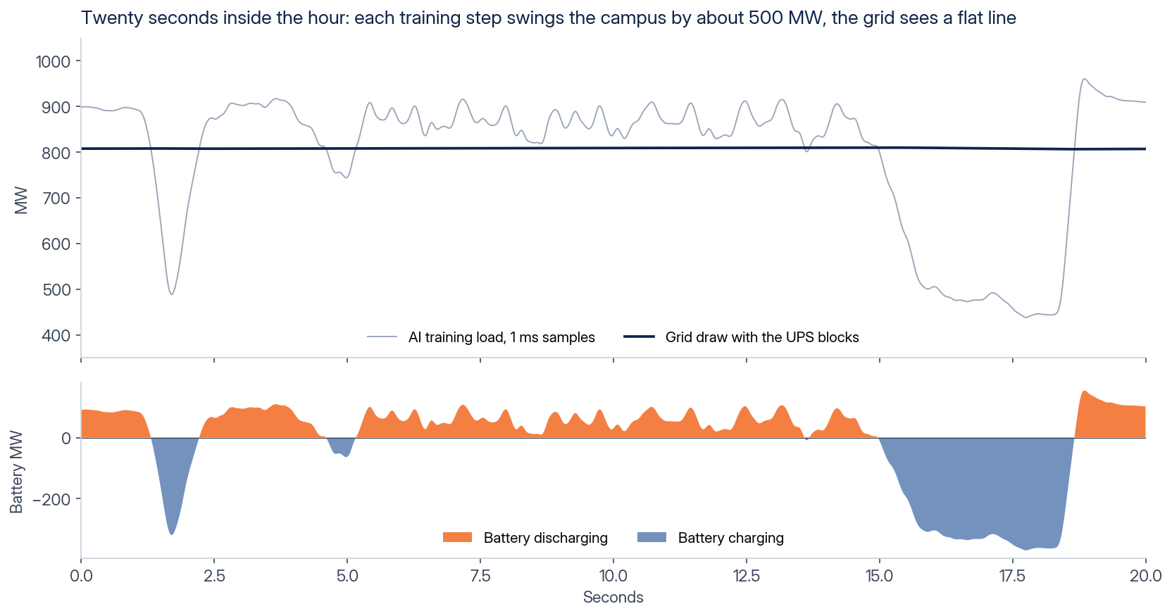
The battery energy storage system (BESS) absorbs training swings that move in under a second, and damps power oscillations between the load and the supply. Power at the point of interconnection (POI) changes more slowly than the compute load.
The UPS block controller takes 4,800 samples per second and makes a decision in under 1 ms. The block responds in 3 ms from measurement through command to the converter. The EMS supervisory loop runs once per second.
The simulation tracks raw load, smoothed connection power, battery charge and discharge, and state of charge (SOC), the available battery charge. These traces show the modeled duty across the displayed time range.
ENERGENCE / POWER SMOOTHING, TWENTY SECONDSA 1 GW campus running one training job, at 1 ms. Each training step swings the load by about 500 MW, in grey. The grid draw in navy stays flat. Below, the battery discharges in orange and charges in blue.
ENERGENCE / POWER SMOOTHING, LIVEThe same run in real time as a rolling twelve-second window.
03 / RAMP RATE CONTROL
Training starts at the permitted pace.
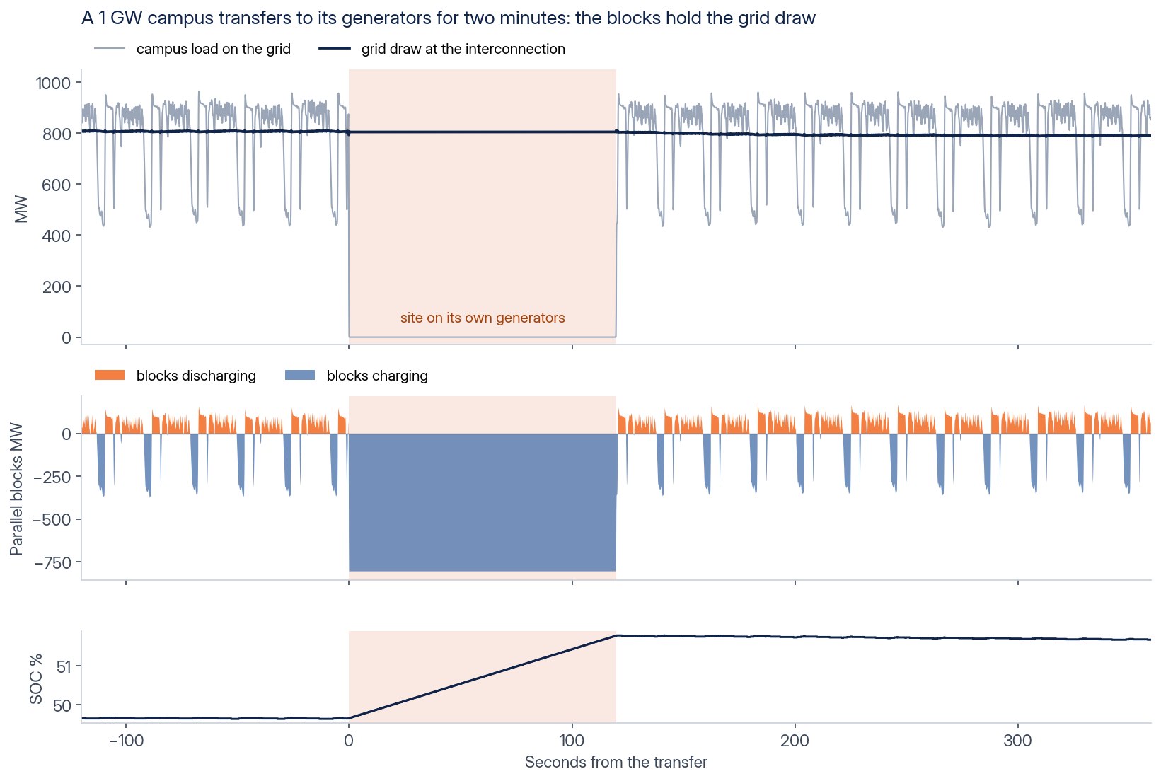
Ramp rate control limits the change in net site load in both directions, in configurable megawatts (MW) per minute. The battery covers the difference while training starts or stops, and protects on-site generators from load steps they cannot follow.
The simulation shows the largest step a site can make: the whole load leaving the grid for its generators and returning.
ENERGENCE / LOAD STEP, SITE TRANSFERA simulated 1 GW campus running one training job transfers its whole load to backup generators for 120 seconds, then returns. The load on the grid drops from about 900 MW to zero and comes back in a step. Parallel blocks with a 3 ms response charge at about 806 MW through the transfer, so the grid draw stays between 787 and 811 MW, and the battery's charge rises from 49.7 to 51.8 percent. Blocks of 1,200 MW and 1,200 MWh, 100 ms data.
ARCHITECTURE CAPABILITIES
Grid forming, islanding and black start.
Grid forming establishes voltage and frequency. Islanding holds a section after separation from the grid. Black start energizes a de-energized section from the battery. The site design defines the operating sequence and load pickup for each capability.
GO DEEPER
Ride-through, power smoothing and interconnection, each with the traces behind it.
Three pages take one duty each, with the simulations and scenario models behind the numbers on this page.
NOGRR 282 ride-through: a grid fault with dual-conversion blocks and with parallel blocks. Fully compatible with ERCOT’s large-load ride-through rule.
Data center power smoothing: the AI load pulse over an hour and over twenty seconds, played live, and ERCOT’s proposed 10 MW in 5 seconds limit simulated at 120 MW and 1 GW.
Data center interconnection: ramp rate control at a training restart, and one EMS for a limited grid connection with on-site generation.
Training continuity and a controlled grid interface.
The battery absorbs load swings, shapes training starts and stops, and supports the section through disturbances. Operators gain a defined reserve and a grid-facing load profile that follows the interconnection limits. Without these functions, load volatility can restrict training schedules and grid events can force lost work to be repeated.
The availability model targets five nines (99.999 %) at the system level with N+1 block failover, one spare block beyond the load requirement. It is evaluated for each site.
Sizing accounts for power conversion, battery duration, redundant blocks and the energy held for ride-through. Market dispatch uses capacity above that reserve. Recharge follows the same ramp limits as the load.
SITE STUDY
The data center viewer connects the layout to the study.
Energence is Battalion’s energy intelligence platform. The data center viewer brings the site layout, energy data and analysis together so the distribution and connection options can be considered in context. The siting study screens the connection capacity available to the load.
Tell us what you are evaluating. An engineer will review your request.
Request information
Request received.
An engineer reviews every request and replies to approved company addresses within one business day.
Your email draft is ready. Send it to complete your request. If your mail client did not open, open the request email or email contact@battalion.energy from your company address with the same details.
We use analytics cookies to see how this site is used. Nothing is used for advertising. Privacy policy